Vol
 Command
line: Vol
Description:
Calculate
volume for 3D models
 TopoLT
toolbar:

Menu:
TopoLT » 3D Model » Calculate volume
Using this command you can calculate volume that forms
between a 3D model and a plan of constant elevation Z or volume that forms
between two 3D models.
To calculate volume you can select 3D model from above or a
plan of elevation Z that represents the above surface of the body for which
volume is calculated and a 3d model from below or a plan of elevation Z that
represents the surface from below (the reference from which positive and
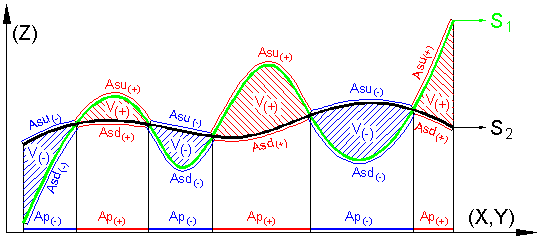
negative volume is calculated). Rule for the way in which positive and negative
volume forms is simple: he part above the reference surface is positive and the
part below this surface is negative no matter if the reference surface is a
plan of constant elevation or a 3D surface (see figures below).
Besides positive and negative volume there are also
calculated plan and surface area (slope area) that corresponds to bodies that
form these volumes. To understand what sloping area is let’s take an example as
area for a mountain covered with a thin layer of snow. The thin layer of snow
is sloping area. In case of volume calculation between two 3D surfaces there
are calculated sloping areas for the above and below parts for positive and
negative volume.
Contour in plan can be limited with a polyline with
condition that this to be inside 3D model or, in case of selecting two 3D
models, inside both 3D models. If this polyline is not introduced then
calculation will be made accordingly to limit given by 3D model or, in case of
selecting two 3D models, accordingly to limit obtained through plan
intersection of the two limits. Contour polylines can also contain arcs. For
contour can also be selected a circle. There are also accepted 3D models that
have holes (missing 3D faces).
Volume is calculate as a sum of 3D bodies (wedges) that are
obtained from spatial intersections between 3D model and plan of constant
elevation or through spatial intersections between two 3D models. Calculation
method is geometrical. There are not used approximation methods and that is why
it is recommended that 3D models you use to be as faithful as possible to the
field.
3D bodies (wedges) can be drawn or not. Choosing to draw
them or not can be done using command Om3d.
Volumes can be viewed or not. Choosing this setting can be
done using command Om3d.
Ed surfaces can have any form, with triangles or grid. There
are accepted any kind of three-dimensional entities excepting those closed in
space (sphere) or those that contain holes in surfaces (cave). When you have
such surfaces where 3D faces are overlapped you can calculate volume by
splitting surface in several pieces.
When you use a smooth grid entity of type “Polygon Mesh” as 3D model it is
recommended that the number of vertexes at interpolation to be big enough so
that the surface to be represented correctly. Before smoothing this kind of
surface choose density on the two directions using AutoCAD variables SURFU and
SURFV.
Before calculating a volume it is recommended to view 3D
model(s) using command VM3D.
Legend:
|
S1 |
- |
plan of constant elevation or
above 3D surface |
|
S2 |
- |
plan of constant elevation or
below 3D surface (reference surface) |
|
V(+) |
- |
positive volume (situated above
reference surface) |
|
V(–) |
- |
negative volume (situated below
reference surface) |
|
Ap(+) |
- |
plan area for positive volume |
|
Ap(–) |
- |
plan area for negative volume |
|
As(+) |
- |
surface area (slope area) for positive
volume |
|
As(–) |
- |
surface area (slope area) for
negative volume |
|
Asu(+) |
- |
surface area up for positive
volume |
|
Asd(+) |
- |
surface area down for positive
volume |
|
Asu(–) |
- |
surface area up for negative
volume |
|
Asd(–) |
- |
surface area down for negative
volume |
Fig. 1 – Case up surface and down reference plan
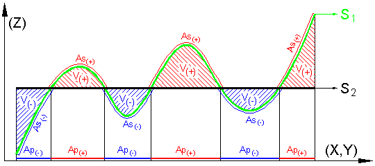
Fig. 2 – Case up plan and down reference surface
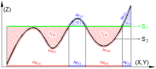
Fig. 3 – Case up surface and down surface (reference)