FormPlns
 Command line: formplns
Description: make and save
Views with plans
 TopoLT toolbar:

Menu: TopoLT » Plan layout » Make
Views with plans
This command is useful
to quick load plans layouts for printing, making unnecessary its cutting,
separated arrangement, moving parts from drawing and by this changing drawing’s
coordinates and so in other way putting changing measured points’ coordinates.
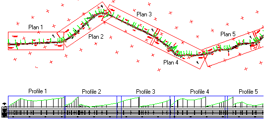
In order to form Views
with plans layouts, or profiles, or whatever you wish to call them, you will
draw rectangles (the most correct way to draw polylines is with command
RECTANGLE, pointing from upper left corner to lower right corner) after which
these will be selected in order. The rotation of these rectangles can be done
respecting the following condition: the bottom segment of the horizontally
drawn rectangle will always be positioned at the bottom of the ViewPort.
Views that will be saved
will have names as Plan1, Plan2, Plan3 … or Profile1, Profile2, Profile3…
After these Views were
saved you will draw plan layout (border, cartouche, legend, etc.) in PAPERSPACE
and one or more viewports (holes in paper space) accordingly to desired
visualization only with Plan or with Plan and Profile. Viewport must have the
same dimensions as rectangle that had been used to save the view.
To be able to load plan
layout number too in the drawing from PAPERSPACE that defines plan you can
insert an attributes block (for example, the whole cartouche) that has to
contain an attribute whose name is defined in Configuration – Plan layout. Inserted block
can have several attributes but one of them must have the same name as the name
introduced at configuration by command TopoCfg section
Plan layout.
To load a plan layout in
the drawing created in PAPERSPACE use command NrPlan.
The following is an
example about forming and saving Views with linked plans.