Creating views with plan layouts
In this exercise you will create views with plan layouts to help you easily load the layouts for printing. In order to form the views, first you have to draw rectangles delimiting the areas you want to print and in accordance with size page layouts.
For more information about this function please see the Help file.
To create views with plan layouts:
1. Open the file 2_Road_with_3Dmodel.dwg from Example folder in ProfLT installation path (by default it is C:\Program Files\ProfLT\Examples).
2. In this example you will build rectangles to split the road in equal parts, and in the same time ensure an overlapping area between two adjacent rectangles.

In TopoLT, go to Plan Layout » Make views with plan layout or type formplns in the command line.
In the command line enter the following:
Type views names… in this example you write the name Plan.
First number for numbering views: enter 1
Select objects: select all rectangles and press Enter
The command end and in the command line displays the number of saved views.
4. After saving the views go to paper space (Layout) and draw the border, title block and one or more viewports.
5. Switch to paperspace (Layout) and go to Plan Layout » Load Plan Layout Number.
Select Viewport allocated for…: select a viewport in the layout
Select block with attribute <NO PLAN>: select the title block
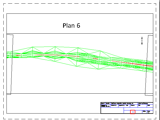
Plan layout number that will be loaded: enter the view number to display in the viewport.

The title block is a block with attributes and the plan number is automatically modified.
6. To load another view go to Plan Layout » Load Plan Layout Number, select the viewport and enter the view number to display.


