Program configuration
The first step that every user has to make when they start a new project is to Configure TopoLT.
In the Configure menu there are several options to configure the program:
Change language (Changing the language of the program)
Program options
Edit codes
Edit layers
Purge drawing

Changing the language of the program
Change language command is used to change the language of the commands and Help file in TopoLT.
Changing the language is made by selecting the .lng file corresponding to the language you want to set and pressing Open. This option can also be accessed from the command line with the Chlng command.

Program options
Here you cand configure the way you work with the program for the current drawing. The configuration data is saved in the current dwg file and if you open a new drawing then the configuration is maintained from the last open of the program.

If you change the plan scale or the point format then the program will ask you to make the following changes in the current drawing:
– deleting and redrawing the graticule according the new scale if it exists;
– scaling the texts in the drawing (without the texts defining the points) according to the new scale factor;
– scaling the polylines thickness according to the new scale factor;
– scaling the point symbols according to the new scale factor; linetypes will be scaled also by changing the LTSCALE variable;
– dimensions scaling according to the new scale factor, keeping the distance between the dimension text and the dimension line in the same measurement unit;
– redrawing the points according to the new scale factor and new format.
Plan section
In this section you can change the following elemets:
– change the scale of the plan;
– change the way points are displayed in plan (point names, elevations or point names and elevations), and for the last two options you can change the decimal precision fot elevations;
– configure point layers.
At the bottom side of this window there is a preview image of all the changes you make.

Points section
In this section you can make the following changes to the way points are displayed in the drawing:
– in Draw Text area you can choose from the drop-down menu the font to be used for texts, the height and width factor and text angle.
– in Style area you can choose the point diameter (in mm) and the point symbol from a list of predefined symbols.
– in Assigning area you can change the block with attributes defining the point by choosing another user made dwg block, selecting the new point code which will be automatically assigned to the new points inserted graphically and the minimum distance between points (useful for eliminating coincident points).
– in Point drawing options area there are options for drawing points from a file or received from an intrument. You can check or uncheck the boxes to modify these settings.
For more information about each option please see the Help file.

Graticule section
In this section you can make settings for the way the graticule will be drawn:
– in Text area choose the font, height and width of the text written on the graticule;
– in Geometry area you choose the distance (line frequency) between two graticule lines, the distance between the selected polyline and the graticule (Border offset) and the scale factor for crosses allocated block.
– in Shape area you can choose the graticule type and the position of the border.

Areas section
In this section you can change the labels used for areas and the options for calculating areas:
– in Labels area you can choose the font, height and width of the text label and the polyline that will enclose the area texts.
– in Surfaces calculation area you can choose different options for displaying the area. For example, in detachments you can create two polylines by breaking the initial polyline or create just one detached polyline.

Tables section
In this section you can change the way tables will be drawn or written to external files:
– in Content area you can choose from Table type what elements to be inlcuded in the table: point name (PN), N, E, Z coordinates and code. On the rigth side you can rename the coordinates axes.
– in Split table area you can set the number of lines for a page and the number of lines for the header in case you want to have a title before the table.
– in Create separate table for stations area you can generate a table only for stations using the specified code.
– in Table in drawing you can choose the font and font height used in the tables generated with Calculate and Record command from Areas menu.

Dimensions Section
In this section you can make setting for the dimensions placed in the drawing so they correspond to the units and scale used in the plan.
When dimensioning parcels in a land registry plan you can choose to supress the dimension lines and arrowheads.

Plan Layout Section
In this section you can set the drawing layout using the printer driver parameters:
– first select the printer you are going to use in the Printer area.
– Margins of printable area and Border margins are determined based on the maximum printing area of the selected printer.
– in Plan layout view area you can see a preview of the layout.
– in Title block (Cartouche) area you can insert title block with or without attributes. You can select the corner where the block will be inserted.
For more details about each option please see the Help file.

Images Section
In this section you can make settings for the way raster images are going to be processed. The following options are applied when using Transform Images and Change Image Format from Images menu:
– images can be saved in one of the following formats: .bmp, .jpg, .pcx, .png, .tga or .tif;
– change the color format and the background for the case when new areas appear in the image after transformation or to increase the processing speed;
– from CAD Drawing Setting area images can be set as transparent (when reinserted in the drawing), nonselectable (when launching TopoLT) or clipped to show only the selected area. The last two options are available only when AutoCAD is used as CAD platform;
– in Cut Image area the images can be cut to keep only the area of interest, the rest of the image is deleted (this decreases the file size and increases the processing speed);
– in Transformation options you can choose various options for image transformations.
For more details about each transformation option please see the Help file.

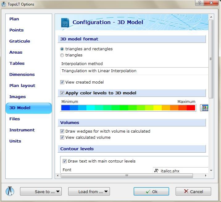
3D Model Section
In this section you can make settings for the 3D model and contour lines:
– in 3D Model Format you choose the method for generating the 3D model (triangles and rectangles or just triangles). For triangles and rectangles option the model will contain rectangles only when two triangles form a rectangle. Creating the 3D model using this option is useful when cutting 3D models composed of rectangles (grid).
– to create presentations or images you can use the option Apply color levels to 3D model, and the faces of the 3D model will be colored according to the levels created for elevations and colors selected.
– by selecting the two options in Volumes area the program will draw the 3D solids which result from intersecting two 3D models or a 3D model and a constant elevation plane and will display the resulting volume.
– in Countour levels area you can change the color and width of the main and secondary contour levels, choose to include the elevation text and format that text, and the distance between two text on the same contour. Also you can choose the method for rounding the contours using quadratic or cubic spline functions and the parametrization method. It is generally recommended to use cubic splines and uniform parametrization.
Files Section
In this section you can make settings regarding the files and extensions used by the program:
– in Used Files area are the files used by the program. For more information on how to modify these files please see the Help file.
– in Coordinates Order from File area you choose the way point coordinates will be read from or written in the file. The coordinate file is an ASCII text file and must contain, in order, point name (point number), N and E or E and N coordinates, point elevation and point code (description). Elevation and point code are optional. The delimiter character can be space, comma (,) or semicolon (;).
– in File extensions area you find extensions for coordinate files, table files and polar points files
– in version TopoLT 10.0 we introduced CSV Files command which allows you to select the delimiter character for CSV files.

Instrument Section
In this section you can configure any type of instrument (total station, field book, PocketPC), and set any format for reading or writing coordinate files.
– in Selected instrument area you can select or modify the selected instrument, add or delete an instrument. To add an instrument you must enter the name, description and extension used to read or write coordinates from/in a file.
– in Serial Communication Settings area you can set communication parameters used to receive or send coordinates. For correctly receiving and sending data through the serial port these parameters must be identical with the ones from the instrument. For the case where in the communication parameters configuration menu from the total station some parameters are missing (such as DataBits or FlowControl) please consult the user manual of the total station to find out the parameter values.
– With the help Data transfer format you can set the read and write method for point coordinates. With the help of N, n, E, e, Z, z, P, C, s, [.], [ ], [^], [/] characters you can build a model for reading/writing coordinates. These characters must be placed on the Data Format line and they represent:
[N,n,E,e,Z,z] = integer and decimal values coordinates;
[P,C] = point number and code;
[s] = plus or minus sign;
[.] = point used for decimal separatin;
[ ] = space character;
[^] = CariageReturn;
[/] = LineFeed;
For more examples of Data Transfer Formats please see the Help file.

Units Section
In this section you can set the measurement units:
– in CAD Settings area you can select Setup CAD units to topographical style which means changing the units in the CAD application so they display the number of decimals according to the decimals allocated for coordinates, angle origin will be oriented to N and angles measured in topographical direction (clockwise). This setting is made when TopoLT is loaded.
– In Measurement units area you can choose metric (m) or english (feet) units.
– Reduction Factor to Measurement Units is used to convert the distances, areas and volumes from the base units (for metric system in m, m², m³ and for imperial system in feet, sq.ft., cu.ft.) in another unit. For example, to change the distances from m to km the reduction factor in 0.001, and to change the areas from m² to ha the reduction factor is 0.0001.
– The Decimals Number for Coordinates is the precision you are working with. All coordinates will be rounded to this precision. Changing this value will influence the way the coordinates are written in files and coordinate tables. This value will also set the precision for fixing points with FixPct (Fix Point) or AutoPct (Automatic insertion of graphical points) commands. Decreasing this value will lead to changes in the values of calculated areas.
– Decimal number for elevations is the number of decimals used to write point and countour elevations.
The text label from Coordinates Measurement Unit is used only when coordinates are written into a table.


