Drawing graphic entities in Google Earth
In this exercise you will draw polygons (closed polylines), paths (open polylines) and points in Google Earth using the new command Draw in Google Earth (GeDraw). The coordinates conversion is made with TransLT software (visit www.topolt.com for more information).
To draw in Google Earth you must respect the following conditions:
– Install Google Earth and TransLT on your computer (both in english). TransLT is used to create the transformation model;
– In both TopoLT and TransLT you must have the same setting for coordinate order, N,E,Z or E,N,Z;
– Coordinates in the drawing must be in a projection system that can be converted to WGS84 ellipsoid;
– In TransLT you must have a transformation model to make this conversion. To define a transformation model open
TransLT and introduce the steps manually or access EPSG database to automatically create the model.
1. First you must set a transformation model in TransLT to make this conversion.
To define a transformation model open TransLT – Parameters calculation and coordinates transformations at Transformation in Steps page.
2. Click the Create model from EPSG database button.

3. In the new window Create transformation model from EPSG database, at Start Coordinates Reference System press Select CRS button to define the start reference system.

For this example select or type these elemenets:
Area of Use: … type Germany
CRS Type: …select from the list projected and press Search button.
All coordinate systems are displayed according to selected criteria.
Select in the table the 31467 code and press OK to confirm the Start CRS.

Follow the same steps for Destination Coordinates Reference Systems.
In this case select as follow:
CRS Type: …select Geographic 2D
CRS Name: type WGS and press Search button.
In the table select the 4326 code and press OK to confirm the Destination CRS.

4. Press the Search Routes button and the program seeks the best route according to selected criteria and displays it at the bottom of the page at Selected Route.

Press OK and a new transformation model is added in TransLT.

5. Open the file Gedraw prezentation Germany.dwg from this path:

6. In TopoLT go to Useful » Draw in Google Earth. Select all elements from the drawing to be draw in Google Earth.
Entities that can be drawn in Google Earth are: 2D polylines (normal, fit or spline), 3D polylines, arcs, circles, ellipses or topographical points drawn with TopoLT.

In order to obtain the right results please follow the conditions from the message below.

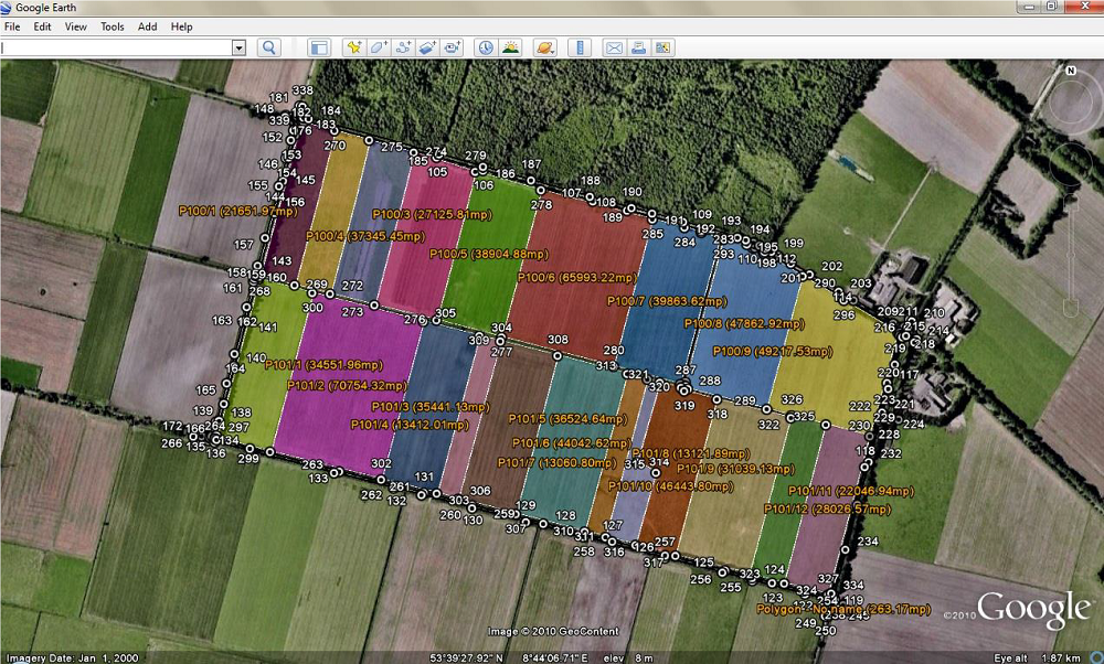
For polylines defined as parcels with the commands Calculate and record (arr), Detach an area (detas) and Multiple detachment (mdetas), information about parcel (number and owner name) are extracted. Area and length are calculated when using this command and the values are written according to the units settings in the program.
Each entity on the left is displayed with the color from the drawing, and on the right side you can add descriptions, modify the color and opacity.
Press View in Google Earth button. Google Earth opens and the selected entities are displayed.


